Running I2C on Pro Micro (3) - Determining Pin States
Table of Contents
- Top
- Parts to prepare
- Items used up to this point
- Wiring
- Interpreting the datasheet (pin-related)
- Implementing on the breadboard
- Basics of state reading
- Interpreting the datasheet (register-related)
- IODIR
- GPPU
- IPOL
- GPIOx
- Reading method
- Program creation (Arduino standard library edition)
- Writing to registers
- Reading from GPIO
- Full program
- Changing polarity
- Using libraries
- Summary
Announcement: A book that significantly expands and revises the content of this article is now available. If you want comprehensive information, please check it out.
In this third article of the series, we will receive the state of the connected device.
In the previous article, we discovered the I2C device, so now we'll determine if a button is pressed at the target address. The device currently connected has the address 0x20, so we'll perform initialization processes on this and check the high/low state of the pins.
Parts to prepare
We'll just connect a switch.
- Switch for operation confirmationx1
- The same one used for reset is OK
Items used up to this point
-
Breadboard (BB-801 etc.) x1
-
Reset switchx1
-
Jumper wire x many
-
Cable to connect Pro Micro and PC
-
MCP23017 x1
-
1kΩ resistorx2
-
Breadboard (BB-801 etc.) x1
- In case you want to separate breadboards. One is fine if it fits
Wiring
Interpreting the datasheet (pin-related)
Let's check what pins the MCP23017 has from the datasheet. When searching for datasheets, you can Google the name or follow links from parts sites like Akizuki if available.
Like academic papers, datasheets start with a summary. It's best to grasp the overall feel by looking at the title and summary, and then check the details as needed. Kind ones even include reference implementations, so it's worth taking a look to save time.
From here, we'll learn how to read using the MCP23017 datasheet.
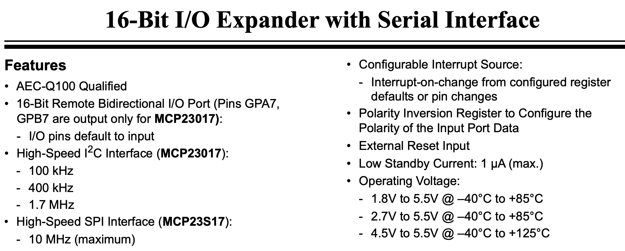
Just reading the summary on the first page provides a lot of information.
-
16-bit input/output with just one of these
-
There's a related IC called
MCP23S17that uses SPI communication. Be careful not to confuse them! -
Supports 400kHz I2C communication (Fast-mode)
-
Also has a state reset pin
-
Works with both 5V and 3.3V
- USB voltage is 5V, Pro Micro often outputs converted 3.3V
-
Need to be careful with GPA7 and GPB7 pins
There are also interrupt-related functions mentioned, but we'll ignore those as we won't use them. The pin assignment is also shown. This is something we'll see many times.

Something we'll see many times
There are some pins we didn't see on the Pro Micro, but they're basically the same.
VDD and VSS can be thought of as VCC and GND respectively. They're abbreviations for Drain and Source, but it's unclear if users need to be concerned about this. Apparently, experts see it differently. For details, see here: What are VCC, VEE, VDD, VSS? About their "differences" and "usage"!
SCK is the same as SCL. It's very complicated. However, even if it's written as SCK, it might not be I2C, so make sure to check before using.
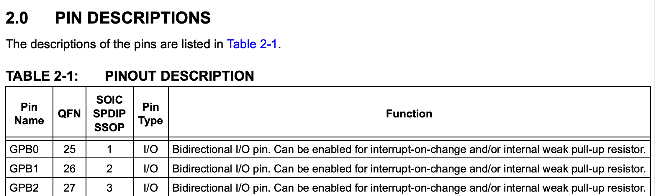
Skipping the difficult waveform pages in the middle, looking at the pin details, it describes the general-purpose input/output pins (GPIO). Here we can see that we can receive input using GPxx.
What needs to be confirmed here is where it says internal weak pull-up resistor. The GPIO of this IC has an internal pull-up resistor, so we don't need to provide one ourselves. That's convenient. Also, as you can see from where it says Can be, it's possible to enable or disable this.

Looking at input pins other than GPIO, it says Must be externally biased. This means we need to connect them properly to GND or VCC. If these are left open, the address might fluctuate or reset unexpectedly, leading to terrible experiences. I've actually experienced this.
By the way, unused input pins should be connected to VCC or GND. It's further recommended to pull them up or down. Ideally, directly connecting to VCC/GND should be fine, but due to potential noise effects or accidental shorts, it's considered good practice to pull them up when properly assembling (see Reference 1, Reference 2).
Also, NC pins are inputs but seem to be not connected internally in the IC, so it should be fine to leave them alone. Connecting them to GND for peace of mind is an option, but we'll leave them alone this time.
Implementing on the breadboard
Now that we have a vague understanding of the connections from last time, let's add a switch. Here, we'll connect it to GPB0.

Achievement: Added a switch to the I2C device
As mentioned earlier, we'll use the internal pull-up, so it's a simple wiring of GPB0 pin → switch → GND.
Basics of state reading
From here on is an important part for programming after connection.
Interpreting the datasheet (register-related)
Let's check the process for reading pin states from the datasheet. However, reading everything is very painful, so I'll introduce just the key points.
First, let's look at the list of configurable registers.

It's complicated because the setting addresses change depending on the value of IOCON.BANK. The default is BANK=0, so we'll proceed without changing this.
There are many, but the important ones are IODIRx, GPPUx, and GPIOx. Also, IPOLx is useful. Each has A pin column and B pin column. Let's look at the details of these.
IODIR

This sets the input/output for each pin. 1 for input, 0 for output, default value is all 0 (output). Since we want input this time, we can achieve this by setting all pins to 1.
However, as stated in the Note, the most significant bit needs to be 0.
GPPU
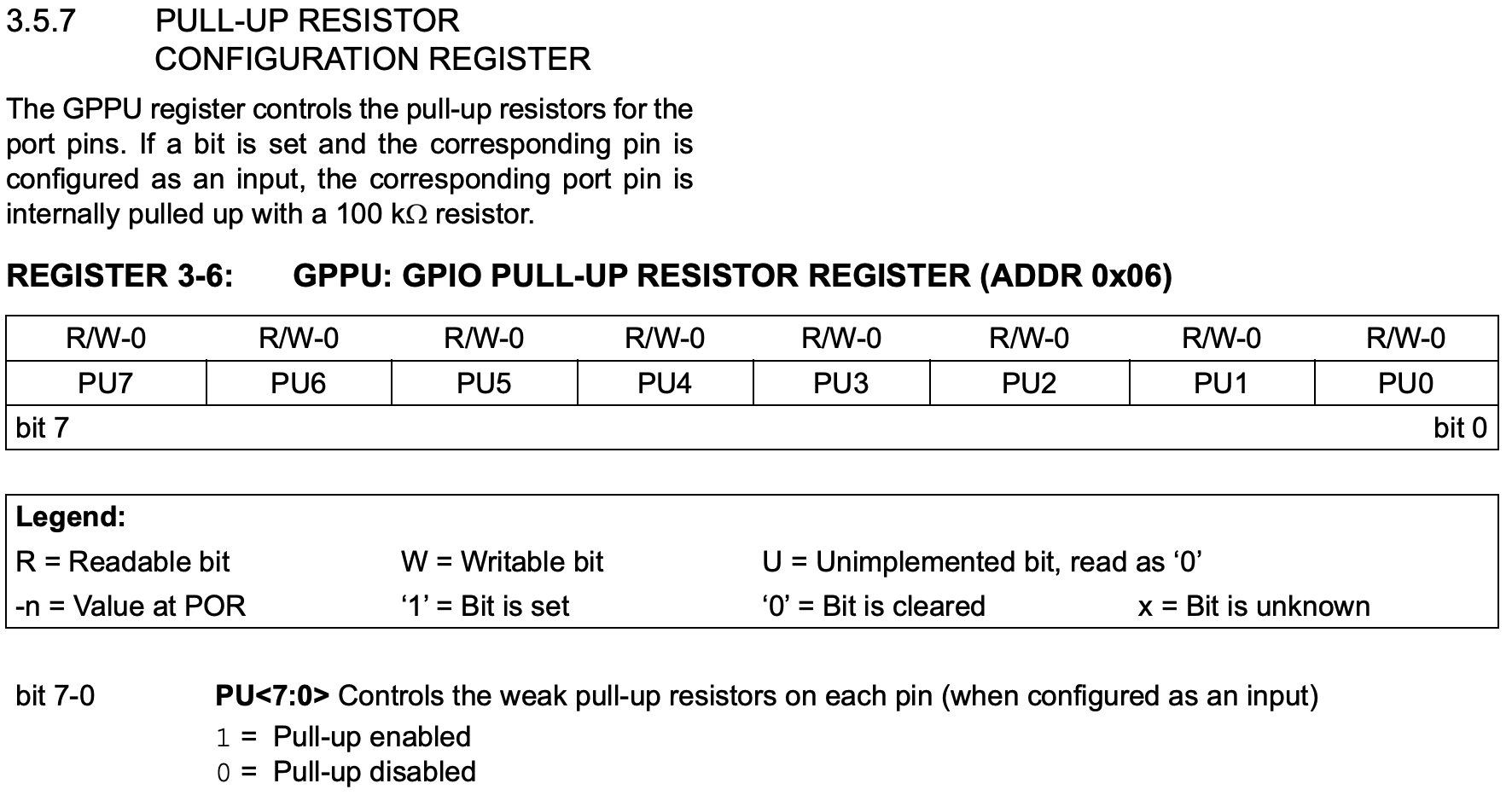
This is the pull-up setting. As mentioned earlier, there's an internal pull-up resistor in the IC, and this setting allows you to enable or disable it. 1 to enable, 0 to disable, default value is 0.
It's written that a 100kΩ resistor is included. This is weak for a pull-up resistor, so consider using an externally provided one if necessary.
IPOL

This setting determines whether to invert the polarity (Low/High) of the input when reporting. The default is as-is.
At first glance, it's not clear what this setting is useful for, but it's actually quite handy. We'll see how to use it later.
GPIOx
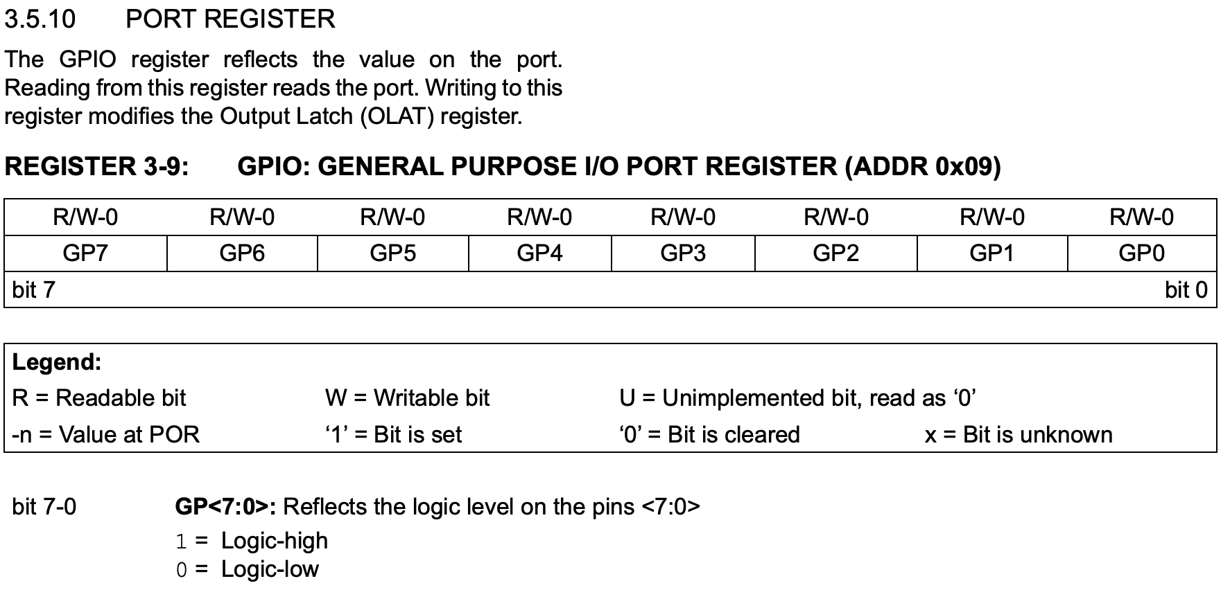
Unlike the above setting registers, this is used for reading values. When you specify this register address and perform a read, it returns the values of each pin in the column.
Reading method
To read the pin state from MCP23017, Pro Micro issues a read command. It then returns in byte units, which Pro Micro processes appropriately. Since MCP23017 has 16 bits, doing this process twice allows you to extract all pin information.
To change behavior, write setting values to the registers. By writing during the setup stage before reading from the pins, you can reflect those settings from the first read.
The register setting values are specified with default values when power is applied. This needs to be checked. Since we can't change the reset on the MCP23017 side this time, if you want to forcibly set to default values, unplug and replug the Pro Micro's power.
Program creation (Arduino standard library edition)
Now let's actually check the input.
MCP23017 seems to be widely used, and there are convenient libraries available. Let's first write using the standard library, and then try using a convenient library.
Writing to registers
To write to registers, use beginTransmission to establish a connection, then use write to write the address and value, and after finishing transmission, call endTransmission.
void writeRegister(byte i2c_addr, byte addr, byte v) {
  Wire.beginTransmission(i2c_addr);
  Wire.write(addr);
  Wire.write(v);
  Wire.endTransmission();
}
Reading from GPIO
Reading pin states requires two steps. First, perform beginTransmission, write, and endTransmission as with writing. Here, specify GPIOx for the address to write.
int readGPIO(byte i2c_addr) {
  Wire.beginTransmission(i2c_addr);
  Wire.write(GPIOA);
  Wire.endTransmission();
  byte received_bytes = Wire.requestFrom(i2c_addr, static_cast<byte>(2));
  if (received_bytes != 2) {
    Serial.println("cannot read 2 bytes");
  }
  uint8_t gpioA = Wire.read();
  uint8_t gpioB = Wire.read();

  Serial.print("gpioA: ");
  Serial.println(gpioA);

  Serial.print("gpioB: ");
  Serial.println(gpioB);

  return gpioA | (gpioB << 8);
}
Here, by specifying only GPIOA and reading 2 bytes, we can obtain both GPIOA and GPIOB values. This is possible because the addresses of GPIOA and GPIOB are conveniently in order. The same method can be used for writing register setting values, but we're doing it one by one for clarity.
Full program
Combining these processes results in the following:
#include <Wire.h>

const byte I2C_ADDR = 0x20;

const byte IODIRA = 0x00;
const byte IODIRB = 0x01;
const byte IPOLA = 0x02;
const byte IPOLB = 0x03;
const byte GPPUA = 0x0C;
const byte GPPUB = 0x0D;

const byte GPIOA = 0x12;
const byte GPIOB = 0x13;

void writeRegister(byte i2c_addr, byte addr, byte v) {
  Wire.beginTransmission(i2c_addr);
  Wire.write(addr);
  Wire.write(v);
  Wire.endTransmission();
}

int readGPIO(byte i2c_addr) {
  Wire.beginTransmission(i2c_addr);
  Wire.write(GPIOA);
  Wire.endTransmission();
  byte received_bytes = Wire.requestFrom(i2c_addr, static_cast<byte>(2));
  if (received_bytes != 2) {
    Serial.println("cannot read 2 bytes");
  }
  uint8_t gpioA = Wire.read();
  uint8_t gpioB = Wire.read();

  Serial.print("gpioA: ");
  Serial.println(gpioA);

  Serial.print("gpioB: ");
  Serial.println(gpioB);

  return gpioA | (gpioB << 8);
}

void I2CSetup(byte address) {
  writeRegister(address, IODIRA, 0xFF >> 1);
  writeRegister(address, IODIRB, 0xFF >> 1);

  writeRegister(address, GPPUA, 0xFF);
  writeRegister(address, GPPUB, 0xFF);

  // writeRegister(address, IPOLA, 0x00);
  // writeRegister(address, IPOLB, 0x00);
  // writeRegister(address, IPOLA, 0xFF);
  // writeRegister(address, IPOLB, 0xFF);
}

void setup() {
  Wire.begin();

  Serial.begin(9600);
  while (!Serial)
    ;  // Leonardo: wait for serial monitor
  I2CSetup(I2C_ADDR);
}


void loop() {
  int gpio = readGPIO(I2C_ADDR);

  Serial.print("gpio: ");
  Serial.println(gpio);

  delay(1000);
}
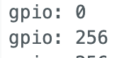
When you write this, it will detect button input every second and output the result. Without input, it's 127, and when the button is pressed, gpioB becomes 126.

State with no input
Changing polarity
Looking at the output values, both GPIOA and B are 127. Why is this?
Because of the internal pull-up, it's high when there's no input. Also, since GPIOA/B 7 is always 0 for output, the result is 0b01111111 = 127 being displayed.
However, when handling in programs, we'd prefer 0 when nothing is done and 1 when a button is pressed. This is where the IPOLx we saw earlier comes in handy. It changes the polarity of input pins for us.
Commenting out the following in the code will change the polarity:
  writeRegister(address, IPOLA, 0xFF);
  writeRegister(address, IPOLB, 0xFF);
When executed, the display becomes very human-friendly.

State with changed polarity
Using libraries
Now that things are working well, let's finally rewrite using a library. Arduino IDE comes with a standard library manager, so we'll use this.
Searching for MCP23017 brings up several options, but we'll use Adafruit's. It conveniently pulls and installs dependencies as well.
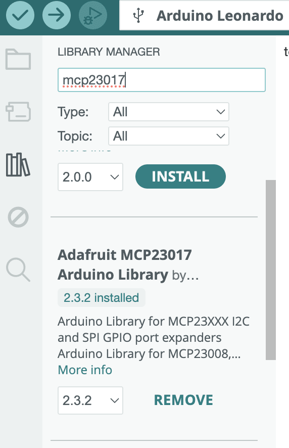
Using Adafruit's library. Convenient.
The code is also publicly available on Github.
adafruit/Adafruit-MCP23017-Arduino-Library
Referring to the sample code, writing something like this will give similar behavior. I couldn't find a function to invert polarity, so here we invert after receiving.
#include <Adafruit_MCP23X17.h>

const byte I2C_ADDR = 0x20;
const byte button_pin = 8;

Adafruit_MCP23X17 mcp;

void I2CSetup(byte address) {
  if (!mcp.begin_I2C()) {
    Serial.println("Error.");
    while (1)
      ;
  }
  for (byte i = 0; i < 16; i++)
    mcp.pinMode(i, INPUT_PULLUP);
}

void setup() {
  Wire.begin();

  Serial.begin(9600);
  while (!Serial)
    ;  // Leonardo: wait for serial monitor
  I2CSetup(I2C_ADDR);
}


void loop() {
  uint16_t gpio = mcp.readGPIOAB();

  Serial.print("gpio: ");
  Serial.println(~gpio);

  delay(1000);
}
Using the library
It's become much cleaner. Let's stand on the shoulders of giants.
Summary
We've finally been able to utilize I2C devices by receiving input. The steps that came up this time will be the same for various devices that appear in the future.
Next time, we'll try connecting breadboards that are far apart using a TRRS cable.